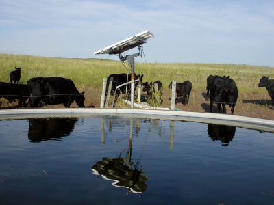
Utilize solar-powered pumps for pumping well water into solar livestock water tanks.
While it’s not unusual for farmers and ranchers to let their animals drink from a creek, pond, or other surface water source, many are switching to alternative methods of supplying drinking water to their livestock. Solar-powered water pumps are easy to install and are a very reliable way to pump water from a well to a ground-level stock tank, or from a surface source of water up to a higher elevation. Some government agencies will even provide cash grants to farmers and ranchers if they agree to fence off grazing lands from nearby creeks and streams and install an alternative means of water provision, such as a well that uses solar-powered pumping methods.

Solar Pump System Components
The most basic form of solar pumping consists of a small direct-current (DC) solar pump, a pump controller, one or more solar modules, a replacement well cap, electrical wiring, and polyvinyl chloride (PVC) piping. Anyone who can use a screwdriver and pipe wrench should be able to assemble a solar pump kit. These systems are very basic. They don’t require power inverters or batteries, and working with 12- or 24-volt DC power is safer than connecting a 240-volt alternating-current (AC) pump to the electrical grid.
Solar pump. Systems requiring only a few gallons of water per minute from wells less than 100 feet deep will typically only need a small 12- or 24-volt DC submersible pump. Deeper wells or setups that need higher flow rates may require submersible pumps in the 48- to 90-volt DC range, powered by a much larger solar array. Solar-powered pumping systems are also available to pump surface water from a stream or lake up to a stock tank located at a higher elevation.
Pump controller. In addition to separate terminals to connect the pump and solar modules, a solar pump controller will also include wiring terminals for optional float switches, which can be used to stop the pump when the tank is full or when the well level is too low. While you could theoretically wire the DC solar pump directly to the solar array, the solar pump controller offers many special features that will increase system performance and provide overload protection for the pump motor.
For example, during early morning and late afternoon hours, the solar array may not provide enough current flow (amperes) to allow the pump motor to start. However, instead of remaining in this stalled condition with the motor windings heating up, some pump controllers can convert excess array voltage into a higher current, which will force the pump to start pumping during dim conditions.
While the reduced voltage during these periods will not allow the pump to run at full speed, additional water flow will be available when the system would normally not pump at all. Solar pump controllers also offer a convenient place to manually turn the pump on and off for service, and LED lights to indicate system status. I strongly recommend that any solar-powered pumping system include a pump controller.
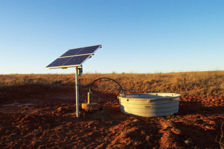
Solar modules. The solar modules should be located as close to the pumping location as possible to reduce wire voltage drop. If located in the Northern Hemisphere, the array should face south. A southwestern orientation will favor locations where overcast mornings and blue-sky afternoons are common. For most farm and ranch applications, you should mount the modules and pump controller on a steel pipe at least 8 feet high to stay above snowdrifts and to mitigate any potential damage from animals and mowing equipment.
A pole mount will also allow you to adjust the array tilt and east-west orientation during initial setup. A tilt angle equal to the latitude of your location will often provide the best overall year-round performance. This will be in the 30- to 40-degree range for the southern half of the United States, and the 40- to 50-degree range for the northern half.
Well cap. Drilled wells will have a protective cap on the top of the well casing where it exits the ground. All submersible well pumps will include either a stainless steel eye bolt or a threaded hole in the pump cap to attach an eye bolt. This will allow you to suspend the pump using a nylon rope, which will prevent strain on the power cable and reduce the danger of the pump pulling loose from the pipe and falling to the bottom of the well.
Most solar pumping kits will include a replacement well cap that has a pass-through fitting for the water pipe, a sealed gland for the power cable, and a matching eye bolt on the bottom side to tie off the safety rope.
Float switch. Whether you’re pumping from a well or a surface water source, both systems use a float switch, which turns the pump on and off based on the water level in the stock or storage tank. Utilizing a storage tank or a larger stock tank will offer more backup water-storage capacity to carry your livestock through multiple days of limited pumping due to cloudy weather.
Anti-freeze bleeder valve. If you’re in an area subject to very cold winter temperatures, you can install an anti-freeze bleeder valve below the frost line but above the static water level in the well. As long as the aboveground piping is sloped back from the discharge point to the well, the anti-freeze bleeder valve will allow any remaining water in the piping to drain back into the well each time the pump shuts off.
How Much Water for Your Livestock?
Before you get started, you’ll want to know what size of system to install. To do this, it will be necessary for you to determine how much water your livestock will need each day. This isn’t as easy to calculate as you might expect because the drinking requirements vary for different animals during different stages of development. Furthermore, all of your livestock will have a different daily water intake depending on the season, the ambient temperature, the type of feed they’re consuming, and whether or not they’re lactating.
To help size your system for different types of livestock, an approximate range for water consumption in a temperate climate for the most common livestock is provided in the table “Daily Drinking Water Requirements” located in the photo slideshow, though the ranges will vary because of the variables previously listed.
While most solar-powered systems pump water directly into a stock tank, systems serving many animals may first pump into a large aboveground storage tank holding several thousand gallons of water. The storage tank would need to be located at a higher elevation than the stock tanks, allowing gravity-flow piping to supply them. Mechanical float valves are available, which open to release water from the larger storage tank when it’s needed and then close when it’s not.

Unlike a standard grid-powered pump, which will provide its rated gallons of flow 24 hours per day, the flow rate for a solar-powered pump will vary from no flow from late evening to early morning, to a maximum flow near high noon. It’s also possible there will be no pumping during inclement weather if there’s too much cloud cover.
However, for an approximation of daily average performance during summer in most of the United States, a solar pump will generally operate from 9 a.m. until 3 p.m. when the solar array faces due south, or 10 a.m. until 4 p.m. for a southwest-facing array. This is an average of six hours of pumping per day during summer months. During this daily time window, you can expect the pump to operate at full capacity for about two hours, 75 percent capacity for another two hours, and 50 percent capacity or less as you move away from high noon. During winter months, this will drop to about four hours of pumping per day.
Because solar pumping systems can only pump when there’s adequate sunlight, the solar pump should be allowed to pump continuously from sunup to sundown, and should only stop pumping when the float switch indicates the tank is full. By adding an elevated storage tank, any water not needed immediately at the stock tank will be available whenever the solar pump isn’t operating.

How Big of a Solar Pump?
Pumps are sized based on the flow rate for a given amount of “feet of head,” called the “total dynamic head.” The total dynamic head is the vertical lift of water, measured in feet, from the level of the water source up to a tank or higher discharge point, plus the head loss caused by friction in the piping and pipe fittings between the two points.
While a larger-diameter pipe will result in less friction-induced head loss, you don’t want to oversize the pipe from the pump to the tank because most solar pumping systems operate at a much lower pressure and flow rate than larger grid-connected AC pump systems. If the flow rate is too low, the water may not have enough velocity to carry sand or gravel picked up by the smaller pump located near the bottom of the well up to the surface. In general, a pipe flow velocity equal to or greater than 2.6 feet per second will alleviate this problem. Check the table “Flow Velocity (Feet per Second)” in the photo slideshow to make sure the flow rate for your pipe size exceeds this minimum.
For a design example, we’ll use a solar pump that’s advertised to pump 4 gallons per minute (GPM) at 100 feet of total head when properly powered. Referring to the table “Feet of Head Loss per 100 Feet” in the photo slideshow, you’ll see that a flow rate of 4 GPM through a 12-inch PVC pipe will result in 17.1 feet of head loss for each 100 feet of piping, which is fairly high. Notice that these table values are feet of head loss per 100 feet of pipe, so if your application requires 250 feet of pipe to reach from the water source up to a tank, you’d multiply the table values by 2.5 (250 ÷ 100 = 2.5). Likewise, if your application only requires 65 feet of pipe, you’d multiply by 0.65 (65 ÷ 100 = 0.65).
Knowing the total dynamic head will help you select an appropriately rated pump for the flow rate that you require. For example, if you were to pump water at 4 GPM through 80 feet of 12-inch PVC pipe from a static water level located 40 feet down a well to a nearby tank located 10 feet above ground elevation, the total dynamic head for this system would be 63.7. Here’s how that calculation would be broken down.
40 feet + 10 feet = 50 feet of head due to elevation
17.1 feet of head loss per 100 feet of 12-inch PVC pipe
× (80 feet of PVC pipe ÷ 100 feet of PVC pipe)
= 13.7 feet of head loss due to pipe friction
50 feet of head + 13.7 feet of head loss
= 63.7 feet of total dynamic head
Because our example pump is specified to provide 4 GPM at 100 feet of total dynamic head, this proposed system should be within the capacity of this pump. However, if the tank was located higher up the hill, the pump’s flow rate would drop, assuming everything else stayed the same.


Jeffrey R. Yago is a licensed professional engineer and certified energy manager with more than 40 years of solar and emergency-preparedness experience. His just-released book, Lights On, addresses living on battery power during a grid-down event.


